OUR BIN ACTIVATOR FOR BULK SILO DISCHARGE APPLICATIONS
IntroductionThe Bin Activator is a well tried and proved piece of equipment for the evacuation of silos. Grain Tech Ltd has found, after many years’ experience, that this is the most efficient and effective method. This paper, therefore, refers to practical knowledge of the unit’s capability. The Bin Activator is a vibratory unit specifically designed for the promotion of consistent mass flow of particulate solids from bulk storage.
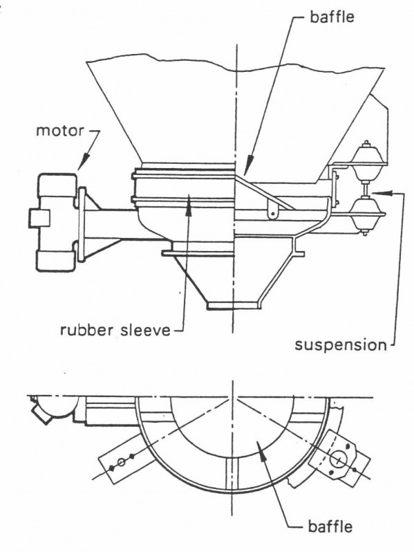
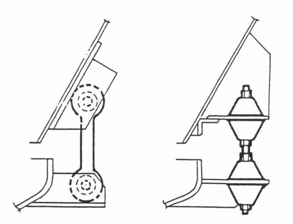
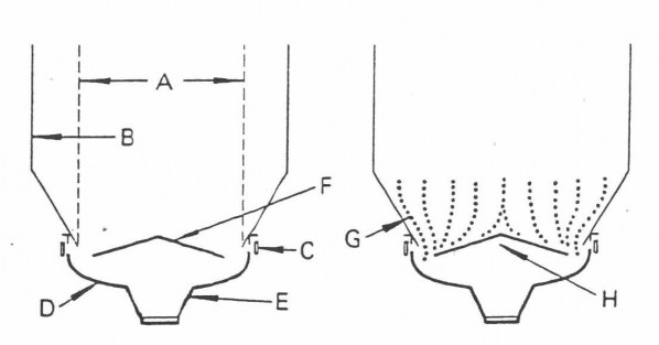
ConstructionIt is basically a pressed steel dished end which is suspended across the mouth of the hopper, usually by means of mild steel rods with rubber anti-vibration mountings. The larger units, however, due to their increased loading, may be supported on hanger links.
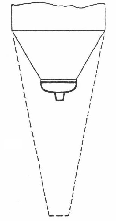
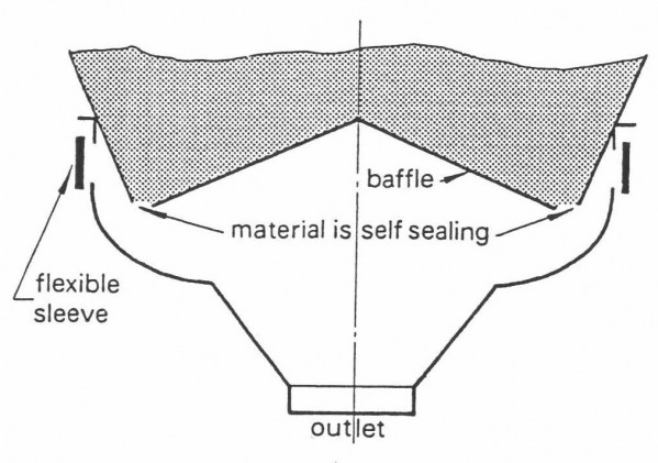
The presence of the isolation units ensures that vibration transmitted to the silo is insignificant when compared with static vertical loading. This means that the unit may be fitted to almost any existing silo with minimum modification. OperationThe vibrating baffle is the key to the unit’s successful operation. It transmits vibrations into the material with maximum effect where baffle and material are in contact. This produces a shear motion in the material which breaks down the cohesive strength and causes the particles to flow from the centre of the baffle towards the annulus between baffle and Bin Activator casing, regardless of the true angle of repose of the material. As the material moves through this annulus the main head load is no longer acting upon it but is being supported by the baffle and the hopper walls. This enables the material to accomplish the most difficult part of the operation. It is now free to converge from the large diameter required for guaranteed discharge to the small diameter required for feeding into the process. This method is not, therefore, subject to the problems associated with applying vibration to a converging hopper in the more conventional manner where material in the area of reduced cross section will be subject to head load. The diameter of the Bin Activator necessary for any application is determined from the diameter of the silo and the material characteristics, but not the throughput. This diameter is usually between one third and one half of the parallel section silo diameter. With certain difficult materials (wood chips, asbestos fibre, distillers’ dark grain with solubles) the Bin Activator is of the same diameter as the silo and this eliminates the transition from cylindrical to conical section, which is a most dangerous area.
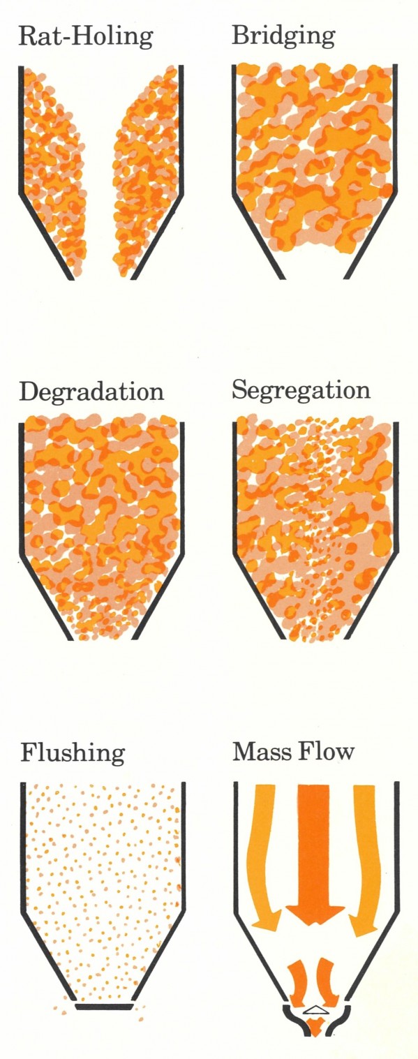
Typical flow problems and the Bin Activator mass flow principle are shown below. The velocity of material from the centre of the bin should be in balance with that of the material around the periphery. As vibrations are transmitted into the material and amplitude gradually reduces with height, there is no preferred bridging point, so that as material is removed from the base more moves downward to take its place. Given that the baffle is covered, the flow should remain consistent, regardless of head of material. One other well known advantage of mass flow is re-mixing of material segregated during silo filling. This also can be achieved.
A Large outlet from stationery section InstallationThe unit is quite simple to install. The angle ring, complete with mounting plates welded to it, is supplied. This is offered up to a suitable diameter opening and welded in position. After strengthening angle ring fixture with gusset plates, the Bin Activator can be bolted up. The time taken to erect a Bin Activator is quite short. Given a prepared silo, lifting apparatus and two men, one 1500mm Bin Activator might take half a day to install.
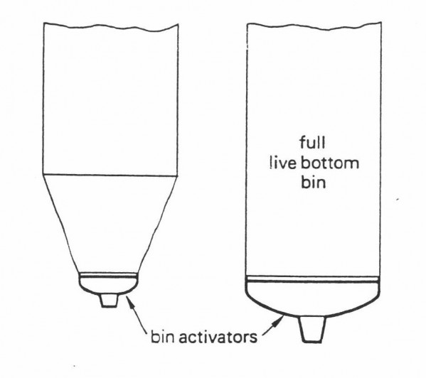
The present range of units (600mm diameter to 3600mm diameter) covers hopper diameters from 600mm to 9000mm. This gives a silo capacity range of approximately 5 to 50,000 cubic feet. A very rough guide to maximum possible feed rate on free flowing material would be 1,000 cu.ft/ft Bin Activator diameter/hour. As with all mass flow bins, level probes can be employed to good advantage. ApplicationListed below are some requirements for different processes that can be achieved with a Bin Activator, 1. Material to stop flowing when unit switched off. Although this characteristic is dependent on material and required throughput, in 80% of installations this can be achieved with no separate valve. When vibrations cease, the material can form its true angle of repose and thus seal the unit.
2. De-aeration with compaction.
When a material has to be metered accurately, it is usually easier to accomplish in a de-aerated state. Since material is often aerated on delivery to a silo, it can be necessary to include a de-aerating system. The Bin Activator can perform this role. 3. Flexibility and consistency of feed rate.
While the Bin Activator is not a feeder but a discharger, it can achieve consistency of 5% deviation from the mean rate, when uncontrolled. If this rate has to be varied however, a metering unit next in line can control the flow and if necessary reduce Bin Activator output to, say, one twentieth of its maximum rating on any given setting without danger of compaction. The freedom from starvation and flushing with this layout enables the metering unit to refine deviation down to, say, ±1%.
4. No degradation
A certain amount of degradation of very friable materials must be expected in any mass of moving materials subject to internal pressures. The Bin Activator does not usually cause any more degradation than would be experienced in a gravity flow bin. Exceptions to this might be lumps of lightly caked material which would break up if too large to feed through internal clearances. Only in extreme circumstances is it impossible to overcome this problem.
5. No segregation.
It has been established that if a mass of material is kept moving, even if only slowly, then segregation does not occur. If the material flow is stopped completely, it is advisable to switch off the Bin Activator unit to prevent segregation and unnecessary compaction.
Conclusion
It is impossible to illustrate the range of Bin Activator applications adequately in the time available because there are hundreds of thousands of these units handling a wide range of materials throughout the world.
|
 Call Us +649 263 6926
- Home
- About Us
- Services
- Products
- Our Food and Chemical Processing Equipment
- Feed-Milling and Material Handling
- Conveying Solutions
- Waste Material Recycling
- Grain Processsing Machinery
- Storage Systems
- Air Handling & Dust Control
- Our Universal Grain & Seed Hulling and Processing Systems
- Weigh-Mix Systems, Bulk Ingredient Handling and Batching Installation
- Our Colour Sorting Machines
- Biomass Processing Systems
- Our Drum Dryers
- "Z" Pattern Bucket Elevators and Inclined Belt Conveyors
- Tube and Chain Conveying Systems
- Magnetic Separators
- Structural Steel Engineering - Concept to Completion
- Silo Bin Activators
- Grain Tech Series Vibrating Fluid Bed Processor
- Contact Us