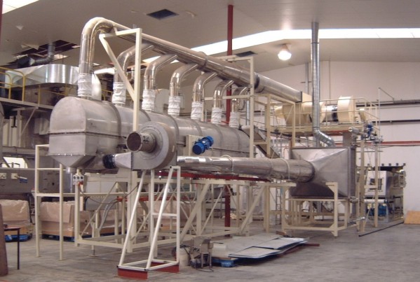
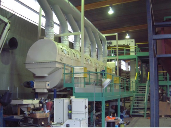
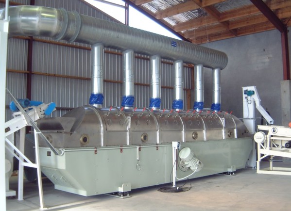
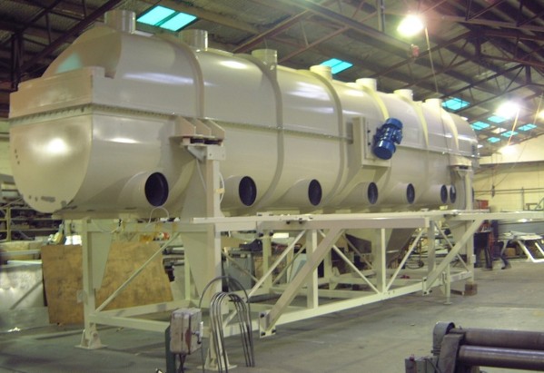
Grain Tech Series Vibrating Fluid Bed Processor
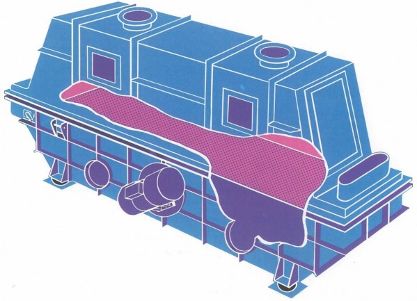
The Grain Tech Series Vibrating Fluid Bed Processor has been developed as a versatile machine capable of adaptation to a number of important continuous processes where intimate contact is required between a gas and a solid. Applications for this machine are the cooling, drying and heating of solids. ArrangementThe solid material is metered to one end of the machine and conveyed along the length of the bed, using well-established vibratory principles. Gas or air is supplied to the base of the processor, which then fluidizes the conveyed solids. Thus enabling close contact to be made between the gas and each individual particle, ensuring rapid heat and mass transfer. The input gas, which could be preheated, pre-cooled or dried, is distributed evenly to the bed according to the process requirements. Likewise, the exhaust gas may be filtered, recovered, recycled or discharged as appropriate. The principle of the Grain Tech Series design allows many advantages over other systems, including far greater control of the fluidized material itself. On all of our machines, there is the option of balancing the air or gas flow to ensure optimum process performance. The input gas is set to cater only for fluidization, so excess gas for solids conveying and hence for the complete suspension of the heaviest particles is not required. This important consideration allows a wider range of particle sizes to be dealt with than on conventional machines. Provision is then made for the exhaust fan system to be set independently so as to control the exhaust gas flow to a minimum. This latter adjustment is made only to ensure no losses of dust to the surrounding atmosphere and also to prevent the unnecessary entrainment of fines into the gas recovery system. Finally, bed depth itself is maintained uniformly by adjustments to an output weir.
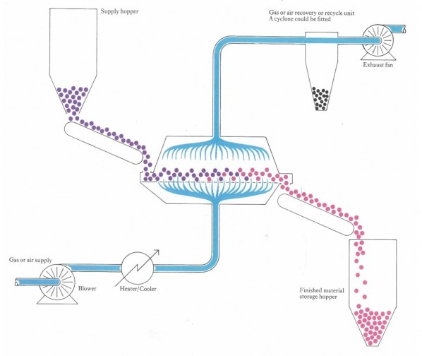
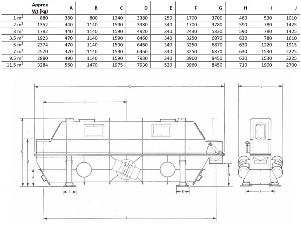
The Grain Tech Series Processor may be sold either as a separate machine or as an installation complete with ancillary heaters or coolers, fans and ducting, filters or cyclones and solids storage hoppers and conveyors. Please clarify the extent of supply in any enquiry ConstructionThe basic machine consists of a vibratory conveying surface surrounded by an upper and a lower gas chamber. This basically simple concept permits the use of most metals, including alloy steels, rubber or plastic-covered steel as constructional materials. The smooth internal design of the machine lends itself to food and sanitary applications. The vibratory movement, which is adjustable, is provided by two low-horsepower out-of-balance electric motors mounted up on the side of the main structure. The adjustment caters for load changes (that were not foreseen during the processing design phase) which can easily be adjusted onsite to meet your needs. The electric motors used are of local manufacture. The conveying surface is made from drilled plate making for a much stronger alternative than cheaper, perforated plate. The unit is mounted or suspended on rubber air rides or coil spring isolators, which successfully eliminate transmission of the vibrations to other parts of the system, the building, or the floor. Advantages • High heat and mass transfer rates between gases and solids. • Versatile, flexible, and highly controllable unit. • Very low installation, running, and maintenance costs, giving huge savings over alternative machines. • Free test facilities, available at our works. • Custom-built machines with complete ancillary systems provided. Specifications
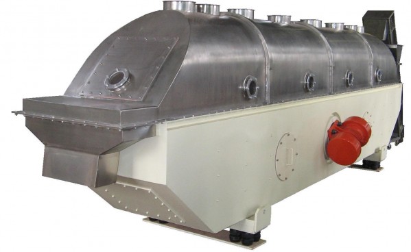
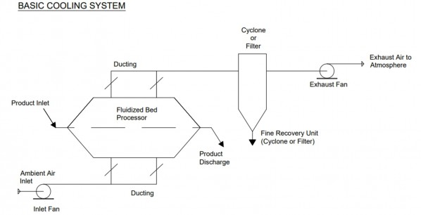
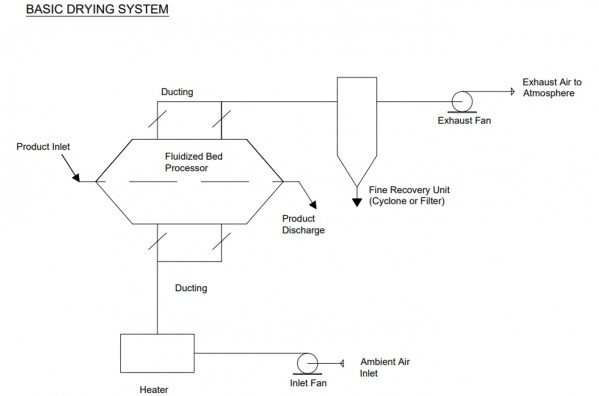
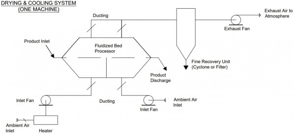
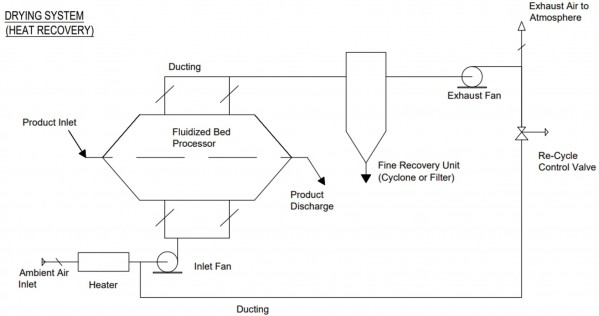
Technical Specifications Operation Features Rapid heating, cooling and drying of powder, pellets, grains and other solids. ❖ Gentle action ensures no degradation to your product. ❖ Heating, drying and cooling in one machine, from 100 kg/hr to 30 t/hr. ❖ Suitable for continuously operated applications in chemical, food, mining and mineral recovery, pharmaceutical and general processing industries. ❖ Controlled adjustment provided over conveying speed and particle separation within the product bed. ❖ Can use any convenient fuel – steam, gas or oil. ❖ Versions available using inert or recycled air or gas. ❖ Low installation and maintenance costs. ❖ Simple to operate. ❖ Continuous or batch systems available. ❖ Can easily be adapted to future changes in your processing line. Introduction & DescriptionThe Fluidized Bed Processor provides a unique system for the rapid drying, heating or cooling of bulk solids by gases. It is an extremely versatile system since it affords full control of product conveying speed, bed depth and retention time and also air/gas volume and temperature. In addition to being able to perform a combination of drying, heating or cooling, the same system can be used for processing a number of dissimilar products. An important feature is that it is self-cleaning. Providing a high-efficiency method of accomplishing heat exchange, the heat transfer media is in complete contact with the product particles, which are also held in suspension thus preventing degradation. The machine's unit length can be subdivided into compartments so that air/gas volumes can be controlled. Thus, in drying, high volumes can be provided at the inlet end where the product is dampest. When handling products with a large variation of particle types and/or sizes analysis, the product will stratify within the bed depth. The larger particles will sit at the bottom where the highest temperature difference occurs. This increases the heat transfer within the machine. The stratification is not noticeable at the discharge from the machine. By adjusting the air/gas flow at the discharge end of the machine, lighter particles could be drawn off into a collection system. Units can be supplied in mild steel or stainless steel or have contact parts in other materials and finished to suit particular applications. All drive units are to IP.W56 specification and flameproof requirements can be met. Being totally enclosed, they are especially suitable for dustproof, weatherproof, and hose-proof applications, and being self-contained, no secondary drive mechanism is required. This dispenses with the need for vee ropes or chain drives or couplings and accompanying guards. Drive units and spares are available on a worldwide basis. Machines are supplied with isolation units, ensuring supporting steelwork is protected from harmful vibrations. Residual vibration in flooring is negligible and this feature, allied to low noise level, allows the machines to be located in the immediate vicinity of plant operators. Being of rugged construction, all machines are capable of withstanding stresses imposed by the most arduous of duties. Prior to delivery, they are shop tested and shipped fully assembled, so that no on-site assembly is required – an important feature where downtime is at a premium. The only maintenance required is the periodic lubrication of drive units and a check on securing bolts. The simple, minimalistic design with minimal parts means that spare part costs are negligible, which further enhances the other important aspects of low operating and servicing costs. Testing Based on previous experience, it is possible to make immediate recommendations as to the system that is most suited to a particular application. When it is not possible to make an immediate recommendation, or as deemed necessary by the client, full tests can be conducted. For test purposes, a 25 kg sample of your product is required. General DescriptionThe standard range of Fluidized Bed Processors consists of machines having five basic features as follows: 1. Lower Plenum: The rough section lower plenum is suitably gusseted and stiffened to ensure that no secondary vibrations occur within the system. At the midpoint, a robust heavy-duty cross beam is fitted which accepts the drive assembly. Along one side of the plenum, there are provided a number of air inlet ports, each of which has beaded edges to facilitate the attachment of flexible connections. These ports can be on either side of the machine. At the discharge end of the machine, a manually operated and fully adjustable weir is provided for the control of product bed depth. The plenum is subdivided across its width when required to afford control of air/gas at each inlet port up into the bed of your product. A clean-out door is fitted at the discharge to clean dust from the plenum. 2. Conveying Deck: This consists of a drilled plate along the full length of the machine with the plate being secured between the lower and upper plenum. The size of the perforation and pattern are carefully chosen to suit the operating requirements of the system. 3. Upper Plenum: The upper plenum is an inverted trough section which is bolted to the lower plenum at a flanged and gusseted joint which secures the conveying deck in position. A product inlet which has a beaded edge is provided at the feed end of the machine and along the side of the plenum sight glasses are fitted. A number of exhaust ports are provided at the top of the unit to accept flexible connections up to the exhaust system. 4. Drive Assembly: The drive assembly consists of vibratory motors, one motor being positioned on each side of the drive bracket in the lower plenum. The motors are fastened by high tensile steel bolts, complete with self-locking nuts, to a baseplate which is bolted to the drive bracket. The assembly is so designed that the angle of the motors relative to the conveying deck can be adjusted. This feature provides adjustment over the conveying speed and particle separation within the product bed. Incorporating heavy series roller bearings specially selected to withstand high centrifugal loads, the motors are of well-proven and robust design. Each motor has a double shaft extension attached to which are captive-out-of-balance weights. The weights can be simply and easily adjusted without the use of special tools or skilled labour, thus affording an immediate change in the condition of the product bed. Each motor has a one-piece bearing housing and inner end cap, providing ease of maintenance. The terminal box is easily accessible, and all motors have totally enclosed sealed end covers and are therefore dustproof, weatherproof and hose-proof. The motors comply with IPW.56 specifications and can meet flameproof requirements. 5. Isolation Units: The complete machine assembly is located on four isolation units. One unit is situated at each corner of the lower plenum and is complete with a baseplate, pre-drilled for bolting directly to supporting steelwork. The isolation units absorb 95% of all dynamic reactions as a minimum. Electrical:Motors are designed for use on three-phase 50Hz supplies at up to 650 volts. Motors are also available for 40 and 60-Hz supplies. All motors are suitable for direct-on-line starting. Operation:The processing media of air or gas is fed under slight pressure into the lower plenum from where it passes up through the drilled conveying deck. The media may be heated or cooled or humidified as necessary. As it passes through the deck it comes into contact with the conveyed product. The air/gas flow is adjusted so that a fluidized bed up to 150mm deep is obtained. The exhausted gas/air is removed and is generally fed through a gas cleaning system consisting of cyclones and/or filters, to remove fine solids that may be present. Extent of Supply:The Fluidized Bed Processor can be supplied as an individual unit or as part of a complete installation. Ancillary equipment would include heaters, coolers, fans, ducting with dampers, filters, cyclones, gas scrubbers and full instrumentation and control panels. The cleaned air/gas can be partially recycled or the heat recovered in a heat exchanger to conserve energy. Solids handling equipment such as feeders, conveyors, elevators and storage hoppers and steelwork can be supplied. Optional ExtrasMaterials of Construction: The machine or parts in contact with the product can be supplied and fabricated from special steels to suit particular installations – stainless steel being the most common alternative to the standard mild steel. Surfaces can also be coated or lined with special finishes. Flexible Connections: These can be manufactured in a wide range of materials. Seals are complete with clips. Starter: The starter provides overload protection for both motors should a fault arise in either. Should one motor fail, the remaining unit is stopped quickly before damage to the system can occur. The starter is suitable for direct-on-line operation. Phase Reversal Braking Unit (P.R.B.U.): For certain applications, it is necessary for the machine to be brought to an immediate stop upon shutdown. To achieve this, a P.R.B.U. can be supplied. Spare Parts List: The recommended spares list comprises the following: 2 off Heavy series roller bearings to suit the vibratory motor. 2 off Isolation units 1 set Motor securing bolts (high tensile steel – 6 bolts per set) 1 set Flexible seals 1 set Flexible seal clips 1 off Sight glass Note: Where downtime is critical, or where multiple machines are installed with motors of a common size, we recommend a spare vibratory motor to be held in stock. Optional Extras: (supplied to order)1 off Starter 1 off Phase reversal braking unit (P.R.B.U.) Note: A specific list of spares is provided for each machine when any special items are listed. Starter: The starter provides overload protection for both motors should a fault arise in either. Should one motor fail, the remaining unit is stopped quickly before damage to the system can occur. The starter is suitable for direct on-line operations. P.R.B.U: In certain applications, it is necessary for the machine to be brought to an immediate stop upon shutdown. To achieve this a P.R.B.U. can be supplied. Typical Installations
Factors Applied to Fluidised Bed DryerAlthough the range of factors generally applied to Fluidized Bed Drying System can be listed as follows, we make it our practice to custom design and manufacture the dryers according to the physical properties of the raw material to be dried.
Particle size of raw material Particle sizes applied in general are in the range from fine particles of 20-40 to grains of 4-8 mm. However, the particle sizes are greatly influenced by the moisture content. For instance, highly moisture fine particles are liable to cause channelling and separation (by particle sizes) phenomena making it impossible to set up a proper fluidization velocity.
Moisture content in the raw material Although there are various cases in this respect according to the physical properties of the material, our experience tells us that it is possible to apply this dryer to the comparatively loose material containing moisture to the extent that when the material is pressed into a lump by a slight grasp but is easily loosened.
Moisture content in the dried product In the course of fluidization, the grains become very active and are mixed with the gas (hot air) very vigorously. Therefore, the moisture content after the first stage drying process is very low such as 1-3%, with a further reduction of moisture content (even to the second stage drying level) by controlling the retention time.
Gas (hot air) temperature As the gas blown into the fluidizing area makes a momentary heat exchange uniformly with the particles, the gas temperature is much reduced in the very small space near the bottom of the Fluidized Bed. Therefore, the use of hot gas at a comparatively high temperature is effective for the drying process which essentially performs evaporation on the surface of particles. The hot air (gas) temperature is established both from the thermal and mechanical properties of the material.
Velocity of the gas for fluidization In the case of the Fluidized Bed in the actual equipment, it is general that the air (gas) velocity (V) is roughly determined by the terminal velocity (Vt) of the particles in a typical diameter. According to the majority of our past records, it is established in the range of V = (0.1 – 0.8) Vt. In the case of fine particles, the air velocity is set taking into consideration all such factors as moisture content, the secondary agglomeration caused by static electricity, the activity of the fluidized layer, and the effects of perforated plate and dusting.
Height of fluidized bed When the still layer is fluidized more and more furiously, the whole Fluidized Bed will start to simulate a piston-like up-and-down action. This phenomenon is known as “slagging”. We design the height of the static bed at a point between 50-800mm, which is lower than the maximum height of the bed at the time of slagging, besides taking into consideration the vessel’s diameter and dusting and pressure loss to be caused by slagging. The height of the Fluidized Bed normally becomes double or thrice as much as that of a still layer, although there is as much difference as the difference in grain sizes of the particles. Therefore, we make it a practice to confirm the height by making preliminary tests each time.
Perforated Plate The design of a Perforated Plate is decided by such factors as the uniform formation of the Fluidized Bed and the degree of pressure loss (from the economical viewpoint of the Blower). Both of the factors are dependent upon the size and activity of the particles. From our past records, however, the perforation is designed within a range of 0.5-5mm perforation diameter, 0.01-0.25 opening ratio and 10-100mmAg. pressure loss. If requested for a special specification, we manufacture Slit Plates too.
Heat Capacity Coefficient The heat transfer coefficient (h) between gas and particles in the Fluidized Bed is not necessarily large. However, since the raw materials particles size is generally small and the surface area (a) of the particles per unit volume of the Fluidized Bed is accordingly very large, the heat capacity coefficient (on volume base) becomes as large as 2,000-6,000 Kcal/m2 .h.˚C. This is the reason we can make the receptacle (vessel) comparatively small.
Heat Transfer Coefficient (U) of the Heat Transmission Tube Units Generally speaking, the U value of the built-in Heat Transmission Tube Units is high when the space ratio of the Fluidized Bed is low. But, the main factor that decides the U value is the contamination of the surface of Heat Transmission Tubes. From experience, we can expect U values as high as 80-200 Kcal/m2 .h.˚C ( on the basis of heat transmission area) available with this dryer. Process Flow Diagrams
EnquiresPlease send all inquiries to Grain Tech Ltd, giving details of the solids and gases to be handled. Information on the solids such as particle sizes and shapes, bulk densities, temperatures and suitable materials of construction, will be required. Supply required. If auxiliary heat exchangers are required, please indicate available heating or cooling media, and also if cyclones or filters are preferred. |
 Call Us +649 263 6926
- Home
- About Us
- Services
- Products
- Our Food and Chemical Processing Equipment
- Feed-Milling and Material Handling
- Conveying Solutions
- Waste Material Recycling
- Grain Processsing Machinery
- Storage Systems
- Air Handling & Dust Control
- Our Universal Grain & Seed Hulling and Processing Systems
- Weigh-Mix Systems, Bulk Ingredient Handling and Batching Installation
- Our Colour Sorting Machines
- Biomass Processing Systems
- Our Drum Dryers
- "Z" Pattern Bucket Elevators and Inclined Belt Conveyors
- Tube and Chain Conveying Systems
- Magnetic Separators
- Structural Steel Engineering - Concept to Completion
- Silo Bin Activators
- Grain Tech Series Vibrating Fluid Bed Processor
- Contact Us